Customer 3D Printer Transformation
My Journey optimizing a hobby 3D printer into a more capable, commercial machine
Design objectives of this project:
Test the limits of a 'good' commercially produced 3D printer by looking at...
Print Speed
Strength of Printed Parts
...then design modifications that will extend the printer's performance.
Add additional functionality
Lights & Cameras
Remote Operation
Heated Enclosure
What Is A ‘Good’ 3D Printer
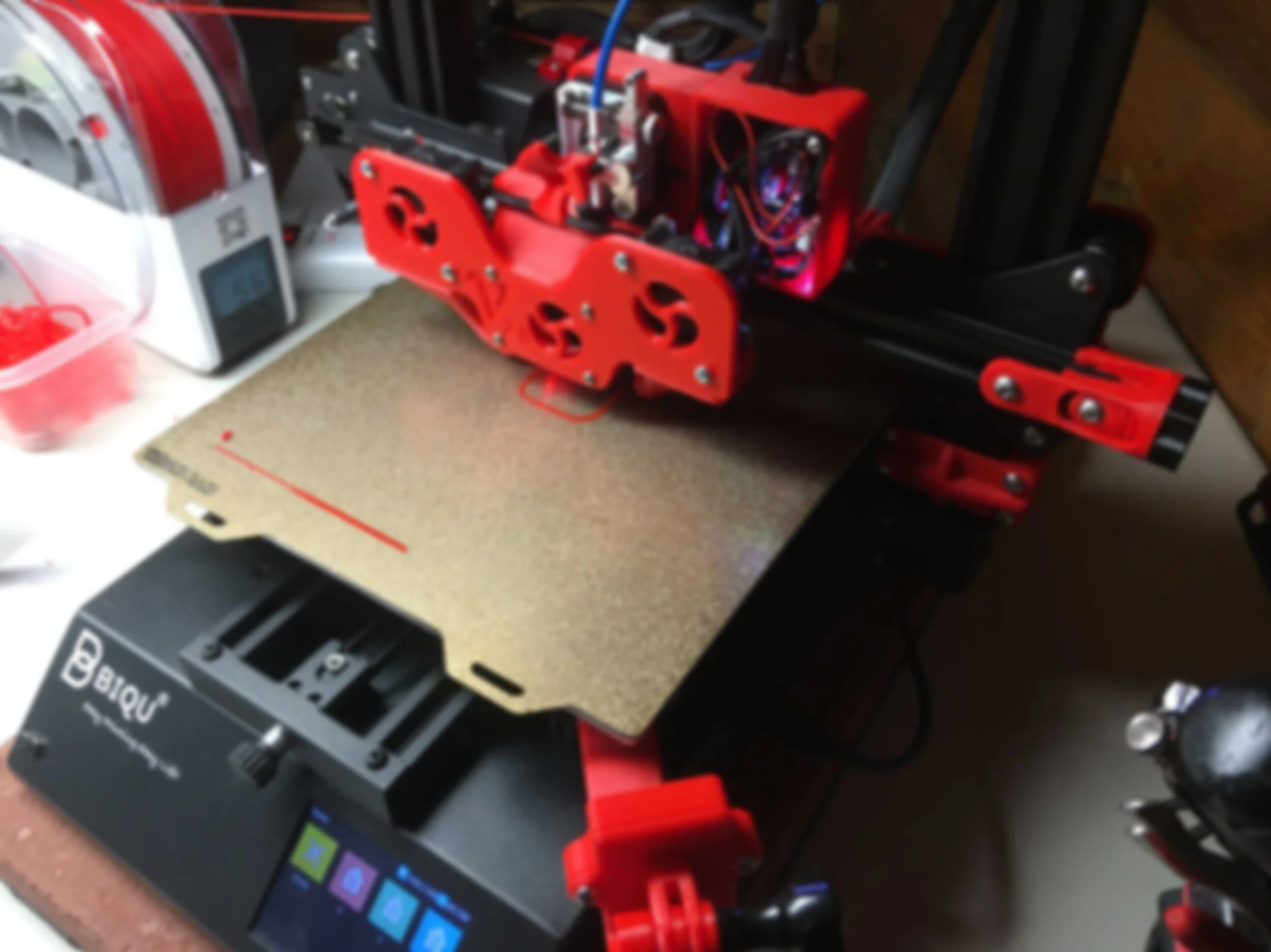
This is a very subjective answer. For me I wanted a reasonably priced unit that has solid, name brand electronics with a lot of documentation. Since I am also an ‘electronics guy’ I wanted a system that allowed for immediate expansion. The BIQU B1 3D printer is decently constructed and has good motion systems.
This BIQU B1 3D printer fit my specifications, also has good motion systems, is decently constructed and has a lot of online documentation. The wiring harness even had clearly labeled wires.
Once I learned as much as I could with the stock 3D printer it was time to do the first modifications.
Many Test Parts
Learning the Limits...
I printed hundreds of parts, keeping detailed notes on each print. Every part is numbered (as seen throughout these images) so I can refer back to the setting used.
II applied the ‘Scientific Method’ throughout this process:
Make an observation
Ask a question
Form a hypothesis, or testable explanation
Make a prediction based on the hypothesis
Test the prediction
Iterate: use the results to make new hypotheses or predictions
Hotend Design #1
Hotend is the group of components that heat up and extrude molten plastic that is added layer by layer for a FFF ( Fused Filament Fabrication) style printer.
Yes, my first Hotend design was larger than the stock system so I could test different configurations of vents, fans, lights and camera locations.
Also I had an interesting design challenge. Most hobby 3D printers use what is called a Bowden type drive system but I wanted to use a Direct Drive system.
There isn't a filament feed system on the BIQU B1 so I used an incompatible direct drive unit and engineered adapter components to make it functional. I chose a direct drive feed because it's faster and more efficient.
I wanted to use a touch probe (white component to the left on the bottom left image) to obtain proper offset distances to the printing surface.
Final Assembly For Hotend Design #1
TI only had the BIQU B1 to print parts so all the enhancements to the machine needed to be designed and printed before I could assemble and test them.
The key was to check and double check all the parts. Once the 3D printer was down no more parts could be made until final assembly of the new system. The vents were challenging prints because of large overhangs. I overcame this challenge using the knowledge gained from printing and testing extreme features, almost 3D printing in air.
Added Motion Components
One of the few downsides of a Direct Drive Hotend is the added weight of the extruder. To resolve this I added a second Z-Axis motor (straight up movement) and drive screw (center image). Both motors were then coupled to a drive belt system I designed (top image). I added markings to help track the drive system.
Another component I added was a belt tension system (lower image) to keep the belts properly tensioned during my planned higher operational temperatures when the 3D printer would be installed in a heated enclosure.
Hotend Design #2
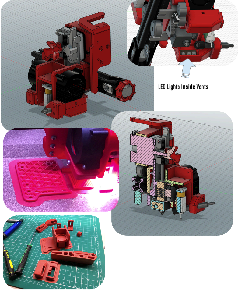
Once all the testing was complete it was time to design a smaller and more compact Hotend. Every millimeter was important and it took a lot of ‘thinking outside the box’ to tightly fit all components in such a small form factor.
I am very proud of the Hotend cooling vent LED design. The cooling vent airflow cools the plastic as soon as it's bonded with the previous printed layer. I needed to illuminate the nozzle tip for a micro camera (as discussed below) so I could observe the print at the tip end. I realized that both the light and air have to converge at the same spot but there was very little space for proper airflow and lighting and still be able to view the Hotend tip? from the camera. Placing the lights inside the vents fulfilled these requirements.
Simple yet functional.
Final Assembly For Hotend Design #2
A total of 34 wires connect the Hotend to the rest of the printer, in a very contained / tight area. The motion control turned out to be the easy part.
As a side note, I got the idea from a 3D printer discussion group about visualizing the cooling vent airflow around the nozzle tip. Use a shallow plate of water. After a few iterations I achieved perfect alignment.
I did computer modeling, but sometimes ‘real-world’ testing can get the best results.
After adding additional fans, motors, lights, cameras and 2 micro-controller boards I more than doubled the amount of wiring from the original stock 3D printer.
Failures
Out of the hundreds and hundreds of parts I have 3D printed failures happened. I learned as much as I could from each one. SpaceX is one of my inspirations when it comes to engineering and design and they have a motto I have lived by - Fail early, learn as much from the failure, really analyze the data and make informed decisions to make the designs better.
Lights 1
I added two different LED lighting systems: the Hotend nozzle lights and an overhead general light since the 3D printer would be in an enclosure.
Most electrical connections require a high-power magnifying glass with 7x reading glasses to get the best view. It's hard to judge scale in a picture- the LED lights are less than 5mm (1/4”) with the solder pads 0.5mm (1/64”). I have years of soldiering experience with electronics so it just takes a little time to set up.
Lights Continued
The top image shows the vents with LEDs mounted inside during the final power test before mounting to the rest of the Hotend assembly.
Yes, they are RGB (Red Green Blue) LED lights. They can produce any color and light level needed. I use color to broadcast different operational modes and functions. When the 3D printer is at idle (as pictured) it just cycles through all the colors.
When Hotend is warming up it goes from blue to red, fully red when system is at temperature, flashing red equals error, etc. It is convenient to know from across the room what state the 3D printer is in.
Cameras & Remote Control to phone
The first camera I wanted to keep stock until I designed a replacement. This camera is just a little larger than a Quarter coin (left upper image).
I switched not long after to an IR (infrared) camera with IR LED lights so the camera can view the 3D printer in complete darkness.
I carried the hexagonal pattern style throughout the design and made several improvements such as adjustable height and GoPro mounting features.
At the same time I researched and installed additional software to the newly installed micro-controllers that processed (what kind of data) data and camera data. This allowed me to view and control the video through my phone.
On my local WiFi network I can view real-time video and control the printer. With a bunch of programming I can view 1 second pictures and monitor/control the 3D printer using SSL encryption (same as Online Banking) on cellular from anywhere.
Cameras & Remote Control to desktop computer
From the very start I really wanted to see exactly what was going on with the nozzle to printed layer interface. Everything that happens comes down to how the plastic is built up layer by layer for FFF 3D printing.
The camera has to be very small but more importantly it has to be magnified. There was a lot of testing and research that went into this addition.
I finally came to the solution using a nano lens (2mm in diameter). I had to use sewing needles to assemble my lens housing. The middle left image shows the first video from the camera.
Now my desktop computer control system is complete with full control and printing awareness. I have an overall view of the 3D printer (small upper left image), the real-time printing layer paths (middle grid image) and the nozzle micro camera view (lower right image). There is so much value to this information and I have made full use of it in tuning the 3D printing process.
For scale, the bottom of the nozzle is less than 0.5mm (1/64”) wide !
First Version of Filtration System
Now it was time to focus on the enclosure to have the ability to 3D print other types of plastics that require higher temperatures.
I did purchase the enclosure but it was too short so I designed and printed a spacer frame.
Some plastics I use release VOCs (Volatile Organic Compounds) so I designed and printed my own custom filtration system.
Side Note: Why design the hexagon shapes throughout the 3D printer modification designs? “The hexagon is the strongest shape known. Not many people know this but if you want something to hold a lot of weight pick a hexagon. Hexagonal patterns are prevalent in nature due to their efficiency.”
The filter walls that separate different filter media are a perfect example. They offer the highest flow-through with the highest strength.
Expansion of the Filtration System
Design for expansion: Since I was not able to get the flow data I required I designed expansibility into my first assembly. Once testing proved that my instinct was correct all I had to do was add a second layer of filter packs.
I have years of experience of turning CAD into real-world designs (upper left image), but it is still really special to be holding the printed part on the same day it was designed.
For all the complexity inside the enclosure the outside is a little sparse. The half clear/white component to the left of the enclosure (bottom right image) is a filament dryer. Some plastics that I use are very hygroscopic (readily taking up and retaining moisture in the air), so the filament has to be stored in airtight containers with desiccant and humidity monitors and actively dried while 3D printing.
I am taking the vast amount I've learned from this project and am carrying it over to my next Custom Designed 3D Printer
In Conclusion
Yes it was a journey, but a very fruitful one. All Design objectives for this project were met:
3x the original printer speeds
Consistently 3D print much stronger plastics with greater accuracy
Much better control and insight in the printing process


